Fender Pro Junior valve amplifier Repair Log
Repair Log – 1996 Fender Pro Junior valve amplifier
Terry Relph-Knight copyright reserved.
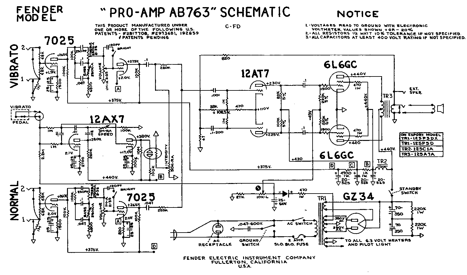
The Pro Junior is a 15W combo amplifier with two 12AX7 dual triode valves and a pair of EL84’s in push pull for the output. The power transformer is rated for 230V and a solid state rectifier produces around +319V for the B+. Note – check if this particular amp has an export transformer with adjustable input taps. Checked and it does, but only for 110V and 230V.
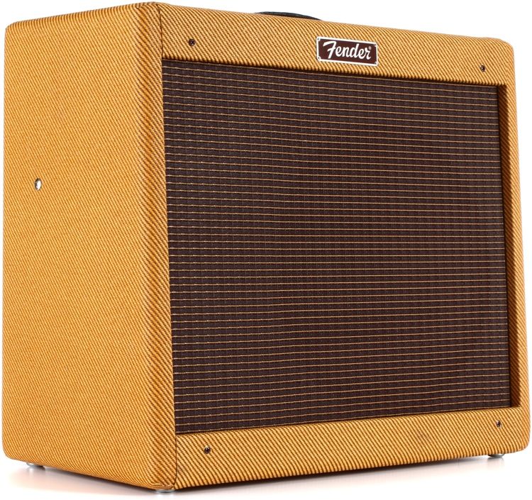
The semi-open back cabinet on this amp is of particle board covered in much worn lacquered tweed. A 10 inch 8 ohm loudspeaker is mounted on a ‘floating’ baffle board with a brown synthetic grille cloth with horizontal baize highlights. Top mounted controls on a chrome plated steel panel with white silk-screen legends – Input jack, volume, tone, power indicator and power toggle switch.
Various problems – Crackling and chronic instability. Also distorted output. Broken handle, and later on a ripped out input jack.
Fender Pro Junior
Work done – When first seen I simply replaced the blown Fender branded 10 inch loudspeaker with a new Eminence Legend 125 and cleaned all the valve bases with contact cleaner. The crackling problems seem associated with the old phenolic bases being fried by the output tubes idling at high dissipation. Later replaced all 4 mini Noval valve bases with ceramic bases and installed an output tube bias adjustment. Set bias to 2.7V (for that particular set of output valves) across one half of the output transformer.
The ripped out PCB mounting input jack was replaced with a floating nylon jack connected via two short wires to the PCB.
At some point the output tubes were replaced with a matched pair of JJ’s and a new handle was fitted.
Parts –
4 x ceramic mini Noval valve bases – £ 13.44
1 x 50K preset – £ 1.64
Stripboard and wire – £ 2
Parts total – £ 17.08
Later on – A problem with almost no output. Turned out the phase splitter DC balance was completely out of wack. One triode was hard on the other off. This problem was extremely difficult to diagnose. It was eventually found to have been due to leakage currents through dirt on the PCB surface. Cleaned the PCB with isopropyl alcohol and the phase splitter returned to proper D.C. balance.
July 2017 – Latest problem – the amp squeals when flat out. First 12AX7 is microphonic. Swapping the first valve with the second cures the problem. However one of the set of JJ EL84 output tubes is running hot – the red silk screen logo on the valve is burnt brown (and the heater filament flares bright yellow at the pin connection when the amp is turned on !!!!).
Work done – Replaced all the valves with new Electro Harmonix valves.
Continued …….
Diagnostics –
Mains voltage setting check – The amp appears to be set to 230V and this is the highest primary voltage available.
As wired 110V230V
Blk/Blu S1B S1B S1B Power Neutral, trans to switch
Black from switch CP4
Blk CP5 CP10 CP6
N/C CP6
Blk/Red CP7 CP7 CP7
N/C CP8
Blk/Grn CP9 CP9 CP9
Blk/Yel CP10 CP8 CP10
Blk/Wht CP11 CP5 CP11 Fuse SW and Power Live
CP5 connects to CP6 on the PCB and both go to the fuse and eventually mains power Live. CP7 connects to CP8 on the PCB, CP11 is an isolated connection parking point on the PCB.
The transformer windings are; BLK/BLU one end of the thermal protection, BLK/RED the other end of the thermal protection and the end of the tapped winding, BLK/WHT is the tap, BLK/GRN is the start of the tapped winding, BLK/YEL is the end of the second winding and BLK is the start of the second winding.
With a complete new set of Electro-Harmonix valves fitted and before any re-biasing, measured B+ 340.8V, red to blue 94.7 ohms 3.6V, red to brown 96.7 ohms 3.13V. Primary currents are 3.6/94.7 =
0.038014784 amps and 3.13/96.7 = 0.032368149. So idle power is 12.818585165 Watts and 10.930723917 Watts. Maximum idle dissipation rating for the EL84 is 12Watts, so before re-biasing right on the dissipation limit for these valves.
Re-biased to 2.2V red to blue we get 2.2/94.7 = 0.023231257Amps or 7.866103485 Watts.
Output power test into an 8 ohm (5%) resistive load. 34V peak to peak @ 1000Hz = 18.0625 Watts
Temperatures of the output pair at 23 degrees ambient, left 130 and right 165 centigrade (viewed from the back of the amplifier).
07/07/17 Ordered a complete set of Electro-Harmonix brand valves
EHX-12AX7-FT 2 £23.00
EHX-EL84-Pair 1 £25.00
Subtotal £48.00
Shipping & Handling £4.25
Grand Total (Excl.Tax) £43.54
Tax £8.71
Grand Total (Incl.Tax) £52.25
